Showing posts with label switching. Show all posts
Showing posts with label switching. Show all posts
Thursday, January 9, 2014
100Khz Multiple Output Switching Power Supply Circuit Diagram
The 100Khz Multiple Output Switching Power Supply Circuit Diagram uses two VN4000A 400-V MOSPOWER FETs in a half-bridge power switch configuration. Outputs available are + 5 Vat 20 A and ±15 V (or ±12 V) at 1 A. Since linear three-terminal regulators are used for the low-current outputs, either ±12 V or ±15 V can be made available with a simple change in the transformer secondary windings.
A TU94 switching regulator IC proVides pulse-width modulation control and drive signals for the power supply. The upper MOSPOWER FET, Q7. in the power switch stage is driven by a simple transformer drive circuit. The lower MOS. Q6, since it is ground referenced. is directly driven from the control !C.
100Khz Multiple Output Switching Power Supply Circuit Diagram


Friday, December 27, 2013
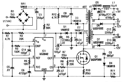
Build a 5v And 12V Ac Powered Switching Supply Circuit Diagram
How to Build a 5v And 12V Ac Powered Switching Supply Circuit Diagram? This supply uses an SGS-Thomson UC3842 IC in an off-line flyback regulator, providing + 5 V at 4 A and ± 12 V at 300 mA. This enables a small high-frequency (50 kHz) transformer, to handle large amounts of power that are normally handled by a 60-Hz transformer.
Q1 is a 5-A 500-V MOSFET, and the diodes are fast-recovery types. T1 has a 45-turn primary winding of #26 wire. The 12-V windings are each 9 turns of #30 wire, bifilar wound. The 5-V winding is 4 turns of four bifilar #26 wires. The control (feedback) winding is two bifilar, parallel 10-turn, #30 windings. The core is Ferroxcube EC35-3C8 with a 3/s` center leg.
5v And 12V Ac Powered Switching Supply Circuit Diagram
Wednesday, April 10, 2013
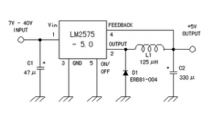
5 Volt Switching Regulator Power Supply
The switching regulator power supply used LM2575-5.0 on this schematic. You can make the stable voltage by using the 3 terminal regulator like LM317. However, because the output electric current and the inputted electric current are the same approximately, the difference between the input electric power (The input voltage x The input electric current) and the output power (The output voltage x The output current) is consumed as the heat with the regulator. Because it is, the efficiency isn�t good.
Data sheet for LM2575
SIMPLE SWITCHER 1A Step-Down Voltage Regulator
http://www.national.com/pf/LM/LM2575.htm
Subscribe to:
Posts (Atom)