Friday, December 27, 2013
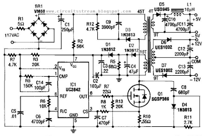
Build a 5v And 12V Ac Powered Switching Supply Circuit Diagram

Monday, October 7, 2013
220V AC Lamp Toggle Switch
Compact, transformer less circuitry No relays employed
Due to the low current drawing, the circuit can be supplied from 230Vac mains without a transformer. Supply voltage is reduced to 12Vdc by means of C1 reactance, a two diode rectifier cell D1 & D2 and Zener diode D3. IC1A, IC1B, R2, R3 and C3 form a reliable bounce-free toggle switch operated by P1. R4 and C4, wired to pin #6 of IC1B reset the circuit (lamp off) when power supply is applied. IC1C and IC1D wired in parallel act as a buffer, driving the Gate of the Triac through R5.
Circuit diagram:
 220V AC Lamp Toggle Switch Circuit Diagram
Parts:
R1 = 470R
R2 = 10K
R3 = 100K
R4 = 100K
R5 = 1K
C1 = 330nF-400V
C2 = 100uF-25V
C3 = 100nF-63V
C4 = 10uF-25V
D1 = 1N4007
D2 = 1N4007
D3 = BZX79C12
D4 = TIC206M
IC1 = 4011 NAND Gate
Notes:
- The circuit can be wired permanently to the mains supply as current drain is negligible.
- Due to transformerless design there is no heat generation.
- Low Gate-current Triacs are recommended.
- Obviously, other appliances can be powered in place of a lamp, provided their power dissipation does not exceed about 400W @ 230V
- 110-120Vac operation is easily obtained by simply changing C1 value to 680nF 250V. No further changes are necessary.
- In some cases, e.g. when the controlled device is far from the toggle switch, a pilot LED could be necessary for monitoring purposes. If so, disconnect pin #10 of IC1C from pin #11 of IC1D and wire a LED and its 1K series current limiting resistor across pin #10 of IC1C and negative supply.
- Warning! The circuit is connected to 230Vac mains, so some parts in the circuit board are subjected to lethal potential! Avoid touching the circuit when plugged in and enclose it in a plastic box.
- P1 will SPST Pushbutton
Source :www.extremecircuits.net
Tuesday, April 2, 2013
Electronic Fuse Circuit for 230V AC

The principle of operation this circuit is begin when the current through the load exceeds a level determined by the position of the wiper on the 1k wire-wound pot, this circuit cuts off the load immediately. If S1 is open, the range is approximately 300-650 mA, and 0.8-2A when it is closed.
The key variable in the operation of the fuse is the voltage drop across the power resistor(s) which are connected in series with the load. This voltage drop is directly proportional to the current the load draws. When this current is low, the voltage across the resistors is also small and cannot trigger T1. At the same time the gate of T2 is fed from a little power supply built around a negative voltage regulator. T2 is conducting and the load is on.