Showing posts with label fuse. Show all posts
Showing posts with label fuse. Show all posts
Sunday, September 29, 2013
Fuse Box BMW E46 2005 Diagram
Fuse Box BMW E46 2005 Diagram - Here are new post for Fuse Box BMW E46 2005 Diagram.


Fuse Panel Layout Diagram Parts: outside mirror, parking aid, passenger comp, trunk lighting, radion, rain sensor, rear wiper, reversing light, roller sun bird, secondary air pump, telephone, trailer coupling, tyre pressure, water valve, sinside mirror electrochomic, interior light, light module, make up mirror light, hifting gate illumination, side airbag, sunroof, socket, speed control, sequential transmission, starter interlock, manual soft, navigation, on board computer, diagnose II, monitor, window lift, windscreen washer.
Continue reading...
Fuse Box BMW E46 2005 Diagram


Fuse Panel Layout Diagram Parts: outside mirror, parking aid, passenger comp, trunk lighting, radion, rain sensor, rear wiper, reversing light, roller sun bird, secondary air pump, telephone, trailer coupling, tyre pressure, water valve, sinside mirror electrochomic, interior light, light module, make up mirror light, hifting gate illumination, side airbag, sunroof, socket, speed control, sequential transmission, starter interlock, manual soft, navigation, on board computer, diagnose II, monitor, window lift, windscreen washer.

Saturday, September 21, 2013
Fuse Box BMW 02 Touring Diagram
Fuse Box BMW 02 Touring Diagram - Here are new post for Fuse Box BMW 02 Touring Diagram.


Fuse Panel Layout Diagram Parts: parking and side light, license plate light, instrument lighteng, fog warning light, fog lamp relay, low beam headlight, turn indicator flasher, cigar lighter, jeater blower, clock, iterior light, hazard warning flasher, triling turn indicator, heated rear window, fuel pump, automatic choke, fuel gauge, coolant thermometer, oil pressure telltale, revolution counter, handbrake telltale, stop light, turn indicator light, horn relay, wier motor, washer, reversing lght.
Continue reading...
Fuse Box BMW 02 Touring Diagram


Fuse Panel Layout Diagram Parts: parking and side light, license plate light, instrument lighteng, fog warning light, fog lamp relay, low beam headlight, turn indicator flasher, cigar lighter, jeater blower, clock, iterior light, hazard warning flasher, triling turn indicator, heated rear window, fuel pump, automatic choke, fuel gauge, coolant thermometer, oil pressure telltale, revolution counter, handbrake telltale, stop light, turn indicator light, horn relay, wier motor, washer, reversing lght.
Friday, September 20, 2013
Fuse Box BMW 733i 1982 Diagram And Power Distribution Fuse Box Map
Fuse Box BMW 733i 1982 Diagram And Power Distribution Fuse Box Map - Here are new post for Fuse Box BMW 733i 1982 Diagram And Power Distribution Fuse Box Map.


Glove Box Light; Heated Door Lock; Ignition Key Warning/Seatbelt Warning; Interior Lights; Lights:Turn/Hazard Warning; On-Boar Computer; Radio/Power Antenna; Active Check Control; Dash Lights; Front Park/Tail/Underhood Light; Rear Marker/LicenseLights; Active Check Control; Backup Lights/Transmission Range Lights; Brake Lining Warning; Cruise Control; Dash Lights; Gauges; Idle Speed Control; Interior Lights; Power Mirrors; Power Windows; Trunk Light, Fuel Delivery/Evaporative Control; Idle Speed Control, Headlights , Cigar Lighters, Active Check Control; Auto Charging Flashlight; Central Locking; Gauges; Radio/Power Antenna; Stoplights/Cruise Control; Warning Indicators, Rear Defogger/Sunroof, Automatic Heater-Air Conditioner; Auxiliary Fan; Vacuum pump, FOglights(RH), Seatbelt Warning; Speedometer; Warning Indicators, Headlights,
Continue reading...
Fuse Box BMW 733i 1982 Diagram And Power Distribution Fuse Box Map


Glove Box Light; Heated Door Lock; Ignition Key Warning/Seatbelt Warning; Interior Lights; Lights:Turn/Hazard Warning; On-Boar Computer; Radio/Power Antenna; Active Check Control; Dash Lights; Front Park/Tail/Underhood Light; Rear Marker/LicenseLights; Active Check Control; Backup Lights/Transmission Range Lights; Brake Lining Warning; Cruise Control; Dash Lights; Gauges; Idle Speed Control; Interior Lights; Power Mirrors; Power Windows; Trunk Light, Fuel Delivery/Evaporative Control; Idle Speed Control, Headlights , Cigar Lighters, Active Check Control; Auto Charging Flashlight; Central Locking; Gauges; Radio/Power Antenna; Stoplights/Cruise Control; Warning Indicators, Rear Defogger/Sunroof, Automatic Heater-Air Conditioner; Auxiliary Fan; Vacuum pump, FOglights(RH), Seatbelt Warning; Speedometer; Warning Indicators, Headlights,
Wednesday, April 10, 2013
Fuse Box Toyota 1995 Supra Engine Compartment Diagram
Fuse Box Toyota 1995 Supra Engine Compartment Diagram - Here are new post for Fuse Box Toyota 1995 Supra Engine Compartment Diagram.


Fuse Panel Layout Diagram Parts: A/C magnetic clutch relay, fog light relay, headlight relay, heater relay, fan relay, ABS system, starter relay, daytime running light, horn relay, dimmer relay.
Continue reading...
Fuse Box Toyota 1995 Supra Engine Compartment Diagram


Fuse Panel Layout Diagram Parts: A/C magnetic clutch relay, fog light relay, headlight relay, heater relay, fan relay, ABS system, starter relay, daytime running light, horn relay, dimmer relay.
Sunday, April 7, 2013
Fuse Box Ford 1998 Escort ZX2 ABS Diagram
Fuse Box Ford 1998 Escort ZX2 ABS Diagram - Here are new post for Fuse Box Ford 1998 Escort ZX2 ABS Diagram.


Fuse Panel Layout Diagram Parts: turn lamp, window defogger relay, blower motor relay, power window lock, park lamp relay, engine control.
Continue reading...
Fuse Box Ford 1998 Escort ZX2 ABS Diagram


Fuse Panel Layout Diagram Parts: turn lamp, window defogger relay, blower motor relay, power window lock, park lamp relay, engine control.
Friday, April 5, 2013
Fuse Box Ford 1997 Escort Under Hood Diagram
Fuse Box Ford 1997 Escort Under Hood Diagram - Here are new post for Fuse Box Ford 1997 Escort Under Hood Diagram.
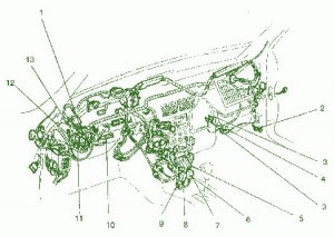

Fuse Panel Layout Diagram Parts: headlamp relay, powertrain control module, fuel pump relay, PCM power relay, fuel pump relay, octane adjust plug.speed control amplifier, instrument panel dimming module, electrnic flasher, blower motor relay.
Continue reading...
Fuse Box Ford 1997 Escort Under Hood Diagram


Fuse Panel Layout Diagram Parts: headlamp relay, powertrain control module, fuel pump relay, PCM power relay, fuel pump relay, octane adjust plug.speed control amplifier, instrument panel dimming module, electrnic flasher, blower motor relay.
Tuesday, April 2, 2013
Electronic Fuse Circuit for 230V AC
This is a design for an electronic fuse that use for 230V AC. This circuit can adjust with an adjustable trip current. This circuit was controlled by variable resistor and regulator IC LM7906 series. This circuit connects directly to 220-230V AC which can be lethal. This design is complete design circuit. The figure of circuit is shown in this below.

The principle of operation this circuit is begin when the current through the load exceeds a level determined by the position of the wiper on the 1k wire-wound pot, this circuit cuts off the load immediately. If S1 is open, the range is approximately 300-650 mA, and 0.8-2A when it is closed.
The key variable in the operation of the fuse is the voltage drop across the power resistor(s) which are connected in series with the load. This voltage drop is directly proportional to the current the load draws. When this current is low, the voltage across the resistors is also small and cannot trigger T1. At the same time the gate of T2 is fed from a little power supply built around a negative voltage regulator. T2 is conducting and the load is on.
The principle of operation this circuit is begin when the current through the load exceeds a level determined by the position of the wiper on the 1k wire-wound pot, this circuit cuts off the load immediately. If S1 is open, the range is approximately 300-650 mA, and 0.8-2A when it is closed.
The key variable in the operation of the fuse is the voltage drop across the power resistor(s) which are connected in series with the load. This voltage drop is directly proportional to the current the load draws. When this current is low, the voltage across the resistors is also small and cannot trigger T1. At the same time the gate of T2 is fed from a little power supply built around a negative voltage regulator. T2 is conducting and the load is on.
Subscribe to:
Posts (Atom)