Showing posts with label simple. Show all posts
Showing posts with label simple. Show all posts
Tuesday, February 4, 2014
Simple Voltage to Current Converter Drives White LEDs
You sometimes need to drive a white LED from one 1.5V battery. Unfortunately, the forward voltage of a white LED is 3 to 4V. So, you would need a dc/dc converter to drive the LED from one battery. Using the simple circuit in Figure 1, you can drive one white LED or two series-connected green LEDs, using only a few components. The circuit is a voltage-to-current converter, which converts the battery voltage to a current that passes through the LED.
You can adjust this current and, thus, the brightness of the LED, by varying resistor R3. If you turn on switch S1, resistor R2 feeds base current to transistor Q2. Q2 turns on, and its collector current, via R3, turns on Q1. Now, the current through inductor L1 increases. The slope of the increase is a function of the value of L1 and the battery voltage. The current through L1 increases until it reaches a maximum value, which depends on the gain of Q1. Because the value of R3 sets the base current drawn from Q1, Q1s collector current is also limited.
White LEDs Circuit Diagram
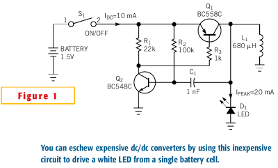
Once the current through L1 reaches its maximum value, the slope of the current through L1 changes. At that instant, the voltage on L1 switches to a negative polarity forced by the changed slope. This negative voltage traverses capacitor C1 and turns off Q2, which in turn turns off Q1. The negative voltage on L1 increases until it reaches the forward voltage of the LED. The peak current through inductor L1 now flows through the LED and decreases to zero. Now, Q2 switches on again, via the current through R2, and the cycle starts again.
By adjusting resistor R3, you can set the peak current through L1 and the peak current through the LED. The brightness of an LED is a linear function of the current through the LED. So, adjusting the value of R3 also adjusts the brightness of the LED.
It doesnt matter which LED you use; the forward voltage on the LED always increases until the peak current through L1 flows through the LED. Different forward voltages of the LEDs yield different on-times (duty cycles) but the same peak current through the LED. With the values shown in Figure 1, the circuit oscillates at a frequency of approximately 30 kHz and delivers a 20-mA peak current through the LED.
The duty cycle depends on the ratio of the battery voltage to the forward voltage of the LED. One advantage of this circuit is that it requires no series-limiting resistor for the LED. The peak current through the LED is a function of the value of R3 and the gain of Q1.[via]
Continue reading...
You can adjust this current and, thus, the brightness of the LED, by varying resistor R3. If you turn on switch S1, resistor R2 feeds base current to transistor Q2. Q2 turns on, and its collector current, via R3, turns on Q1. Now, the current through inductor L1 increases. The slope of the increase is a function of the value of L1 and the battery voltage. The current through L1 increases until it reaches a maximum value, which depends on the gain of Q1. Because the value of R3 sets the base current drawn from Q1, Q1s collector current is also limited.
White LEDs Circuit Diagram
Once the current through L1 reaches its maximum value, the slope of the current through L1 changes. At that instant, the voltage on L1 switches to a negative polarity forced by the changed slope. This negative voltage traverses capacitor C1 and turns off Q2, which in turn turns off Q1. The negative voltage on L1 increases until it reaches the forward voltage of the LED. The peak current through inductor L1 now flows through the LED and decreases to zero. Now, Q2 switches on again, via the current through R2, and the cycle starts again.
By adjusting resistor R3, you can set the peak current through L1 and the peak current through the LED. The brightness of an LED is a linear function of the current through the LED. So, adjusting the value of R3 also adjusts the brightness of the LED.
It doesnt matter which LED you use; the forward voltage on the LED always increases until the peak current through L1 flows through the LED. Different forward voltages of the LEDs yield different on-times (duty cycles) but the same peak current through the LED. With the values shown in Figure 1, the circuit oscillates at a frequency of approximately 30 kHz and delivers a 20-mA peak current through the LED.
The duty cycle depends on the ratio of the battery voltage to the forward voltage of the LED. One advantage of this circuit is that it requires no series-limiting resistor for the LED. The peak current through the LED is a function of the value of R3 and the gain of Q1.[via]

Thursday, December 26, 2013
Simple Micro volt probe Circuit Diagram
The current tracer helps locate a defective IC that is loading down the power supply. The tracer amplifies the small voltage drop caused by current flow along a fraction of an inch of PC wiring and drives an ordinary microammeter. Needle-point test probes are used to contatt the edge of a PC trace and to follow the current to determine which branch the current takes.
One-half of a dual 741 op amp forms a dc amplifier with ac feedback to prevent oscillations and hum-pickup problems.It drives a 50-to-100 µ meter. The other op amp provides a center tap for the 9 V battery supply and zero adjustment with R4. Two diodes protect the meter. Resistor Rl eliminates the necessity for shorting the probes when the meter is zeroed. The value of 1 ohm is large when compared with the resistance of the meter leads plus the bridged portion of PC wiring.
Micro-volt probe Circuit Diagram

If you like this dont forget click on share button
Tuesday, December 17, 2013
Simple Security Monitor
A remote listening circuit. The area to be monitored is connected via a cable and allows remote audio listening.
Starting from the right hand side, the power supply. I have used 12V as a standard power supply voltage, or a 12V car battery may be used. The circuit is in two halves, a remote microphone preamp, and an audio amplifier based around the National Semiconductor LM386 audio amplifier.
Security Monitor Circuit Diagram :

The remote preamp uses an ECM microphone to monitor sound. A direct coupled 2 stage amplifier built around Q1 and Q2 amplify the weak microphone signal. Preset resistor R2 acts as a gain control, and C1 provides some high frequency roll off to the overall audio response. Q1 is run at a low collector current for a high signal to noise ratio, whilst Q2 collector is biased to around half the supply voltage for maximum dynamic range. The power supply for this preamp is fed via R10 and R6 from the 12V supply. C4 ensures that the preamp power supply is decoupled and no ac voltages are present on the power lines. The amplified audio output from Q2 collector is fed onto the supply lines via C6 a 220u capacitor. The output impedance of Q2 is low, hence the relatively high value of C6. C6 also has a second purpose of letting the output audio signals pass, whilst blocking the dc voltage of the power supply.
At the opposite end, C7 a 10u capacitor, brings home the amplified audio to the listening location. The signal is first further amplifier by a x10 voltage gain amplified using the TL071. C8, a 22p capacitor again rolls off some high frequency response above 100kHz. This is necessary as long wires may pick up a little radio interference. After amplification by the op-amp, the audio is finally passed to the LM386 audio amplifier. R14 acts as volume control. R13 and C12 prevent possible instability in the LM386 and are recommended by the manufacturer. Audio output is around 1 watt into an 8 ohm loudspeaker, distortion about 0.2%. If preferred headphones could be used, although Id recommend a series resistor of the same value impedance as the headphones.
Notes:
You can use this in your garden and listen for any unusual sounds, or maybe just wildlife noises. If you have a car parked in a remote location, the microphone will also pick up any sounds od activity in this area. The cable may be visible or hidden, screened cable is not necessary and you can use bellwire or speaker cable if desired.
Source : http://www.ecircuitslab.com/2012/09/simple-security-monitor.html
Monday, May 13, 2013
Simple Analog to Digital Converter

Normally analogue-to-digital con-verter (ADC) needs interfacing through a microprocessor to convert analogue data into digital format. This requires hardware and necessary software, resulting in increased complexity and hence the total cost.
The circuit of A-to-D converter shown here is configured around ADC 0808, avoiding the use of a microprocessor. The ADC 0808 is an 8-bit A-to-D converter, having data lines D0-D7. It works on the principle of successive approximation. It has a total of eight analogue input channels, out of which any one can be selected using address lines A, B and C. Here, in this case, input channel IN0 is selected by grounding A, B and C address lines.Usually the control signals EOC (end of conversion), SC (start conversion), ALE (address latch enable) and OE (output enable) are interfaced by means of a microprocessor. However, the circuit shown here is built to operate in its continuous mode without using any microprocessor. Therefore the input control signals ALE and OE, being active-high, are tied to Vcc (+5 volts).
The input control signal SC, being active-low, initiates start of conversion at falling edge of the pulse, whereas the output signal EOC becomes high after completion of digitisation. This EOC output is coupled to SC input, where falling edge of EOC output acts as SC input to direct the ADC to start the conversion.
As the conversion starts, EOC signal goes high. At next clock pulse EOC output again goes low, and hence SC is enabled to start the next conversion. Thus, it provides continuous 8-bit digital output corresponding to instantaneous value of analogue input. The maximum level of analogue input voltage should be appropriately scaled down below positive reference (+5V) level.The ADC 0808 IC requires clock signal of typically 550 kHz, which can be easily derived from an astable multivibrator constructed using 7404 inverter gates. In order to visualise the digital output, the row of eight LEDs (LED1 through LED8) have been used, wherein each LED is connected to respective data lines D0 through D7. Since ADC works in the continuous mode, it displays digital output as soon as analogue input is applied. The decimal equivalent digital output value D for a given analogue input voltage Vin can be calculated from the relationship
Tuesday, April 30, 2013
Simple Solar charger circuit project using transistors
A very simple solar charger circuit project can be designed using few external electronic parts . This simple solar charger circuit is capable of handling charge currents of up to 1A. Alternate component values are given in the figure for lower current applications.
Circuit diagram:
 Solar charger circuit project using transistors circuit diagram
The only adjustment is the voltage trip point when the current is shunted through the transistor and load resistor. This should be set with a fully charged battery. As the transistor and R3 have the entire panel’s output across them when the battery is fully charged, all of the current from the panel will be going through R3 and the Darlington transistor TIP112, so these must be well heat sunk. Adjust R1 for the trip point, usually 14.4 V – 15 V for a 12 V SLA or a 12 V Ni-Cd battery.
Tuesday, April 9, 2013
A Simple 5 KVA to 10 KVA Automatic Voltage Stabilizer Circuit Explained 220 Volts 120 Volts
The diagram shows a rather simple voltage stabilizer design which can hold huge output power in the order of 5 to 10KVA. The use of SSR or solid state relays makes the output stage easy to configure and very accurate - thanks to the modern SSRs which are designed to trigger massive power in response to smaller input DC potentials.
The circuit is pretty simple to understand. All the opamps are arranged in standard voltage comparator modes.
The presets P1 to P7 can be adjusted as per the required tripping points, which will correspond to the output SSR switching and the subsequent transformer tap selections.The central green TAP is the normal voltage output, the lower TAPs gradually produce higher voltages while the upper TAPs are set for lower voltages.
These TAPs are chosen by the appropriate SSRs in response to the varying AC voltages, thus adjusting the output voltage to the appliances close to normal levels.This circuit was asked by Mr. Alexandar and the SSR data was provided by him.
Parts List
R1 to R9 = 1K, 1/4 watt,
P1 to P7 = 10K preset,
C1 = 1000uF/25V
VR1 = 1K Preset,
opamps = IC 324,
Transformer = Input 230volts or 120volts, Taps - incrementing/decrementing voltage levels (TAPs) as per individual specs.
SSR = 10KVA/230volts = output, 5 to 32 volts DC = input
COMPLETE SSR SPECIFICATION CAN BE FOUND HERE:
http://www.unisoncontrols.com/ssr-dc-to-ac-1ph.php

The circuit is pretty simple to understand. All the opamps are arranged in standard voltage comparator modes.
The presets P1 to P7 can be adjusted as per the required tripping points, which will correspond to the output SSR switching and the subsequent transformer tap selections.The central green TAP is the normal voltage output, the lower TAPs gradually produce higher voltages while the upper TAPs are set for lower voltages.
These TAPs are chosen by the appropriate SSRs in response to the varying AC voltages, thus adjusting the output voltage to the appliances close to normal levels.This circuit was asked by Mr. Alexandar and the SSR data was provided by him.
Parts List
R1 to R9 = 1K, 1/4 watt,
P1 to P7 = 10K preset,
C1 = 1000uF/25V
VR1 = 1K Preset,
opamps = IC 324,
Transformer = Input 230volts or 120volts, Taps - incrementing/decrementing voltage levels (TAPs) as per individual specs.
SSR = 10KVA/230volts = output, 5 to 32 volts DC = input
COMPLETE SSR SPECIFICATION CAN BE FOUND HERE:
http://www.unisoncontrols.com/ssr-dc-to-ac-1ph.php
Wednesday, April 3, 2013
Simple accu charger circuit

Accu charger circuit is very simple and easy to make, because it only requires a few components are also not more than 10 components. Besides easy charger circuit is also very cheap and very efficient.
This circuit requires power supply from a transformer that comes from an AC voltage 220 and diuturunkan be 12-13 volts and then enter to-circuit and 12 Volt DC output allows for charging 12V battery
| Simple charger schematics |
Subscribe to:
Posts (Atom)