Friday, December 27, 2013

Build a 5v And 12V Ac Powered Switching Supply Circuit Diagram

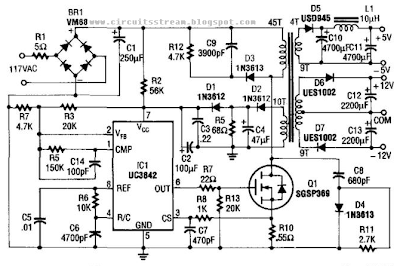
How to Build a 5v And 12V Ac Powered Switching Supply Circuit Diagram? This supply uses an SGS-Thomson UC3842 IC in an off-line flyback regulator, providing + 5 V at 4 A and ± 12 V at 300 mA. This enables a small high-frequency (50 kHz) transformer, to handle large amounts of power that are normally handled by a 60-Hz transformer. 

Q1 is a 5-A 500-V MOSFET, and the diodes are fast-recovery types. T1 has a 45-turn primary winding of #26 wire. The 12-V windings are each 9 turns of #30 wire, bifilar wound. The 5-V winding is 4 turns of four bifilar #26 wires. The control (feedback) winding is two bifilar, parallel 10-turn, #30 windings. The core is Ferroxcube EC35-3C8 with a 3/s` center leg.

5v And 12V Ac Powered Switching Supply Circuit Diagram

5v And 12V Ac Powered Switching Supply Circuit Diagram

Continue reading...

Thursday, December 26, 2013

Simple Micro volt probe Circuit Diagram

The current tracer helps locate a defective IC that is loading down the power supply. The tracer amplifies the small voltage drop caused by current flow along a fraction of an inch of PC wiring and drives an ordinary microammeter. Needle-point test probes are used to contatt the edge of a PC trace and to follow the current to determine which branch the current takes. 

One-half of a dual 741 op amp forms a dc amplifier with ac feedback to prevent oscillations and hum-pickup problems.It drives a 50-to-100 µ meter. The other op amp provides a center tap for the 9 V battery supply and zero adjustment with R4. Two diodes protect the meter. Resistor Rl eliminates the necessity for shorting the probes when the meter is zeroed. The value of 1 ohm is large when compared with the resistance of the meter leads plus the bridged portion of PC wiring.

Micro-volt probe Circuit Diagram

Micro-volt probe Circuit Diagram

If you like this dont forget click on share button
Continue reading...

Wednesday, December 25, 2013

There is no need to get the special training to operate phone jammer

There is no need to get the special training to operate phone jammer .
"Fixed position" be changed to the upper left corner "point X coordinate into a 63" fixed point Y coordinate into a 156 "maximum width" be changed to 102, the frame color, "within the box color, Background color changed to white FFFFFF text color changed to red FF00FF. Set show the effect will be much better. TXT, text is one of the most commonly used text format in the computer, if you want to read and edit the TXT text install YEdit software on the phone. It has a very strong TXT text reading and editing features. After installation, conduct basic settings: Options - Tools - Settings "will open the file encoding to save the file encoding is set for the GB2312, word wrap is set to open. The technical personnel is doing every effort to make phone jammer more effective.
Can now press the "Options - File - New open save the TXT text to open the text, press the" Options - Edit the text to paste Select Find the use of the office suite Quickoffice. 60 version of the Quickoffice the Premier Series is the only one who can edit Microsoft Office documents smartcell phone software on Symbian smartcell phone platform. computer-formatted e-mail attachments directly on the cell phone view and edit additional conversion without the need to do on the computer, and special editorial protection mechanism can keep the original contents of the file. Q: How do I enter Quickword edit mode? To enter edit mode, select "Options - Edit mode so you can directly edit the Quickword document. If there are too many sets of phone jammer , especially after many buildings in the prison implement shielding, it is harder to switch on or off centrally or uniformly.
The Quickword an error when I try to open a Microsoft Word document "doc" file, "do not support the contents of the file, what does this mean? This file have any questions? This situation mostly because trying to open doc file, in fact, RTF (Rich Text Format) files. You can open this file on the computer using Word and then save as DOC format, so that you can successfully open. Note that: similar Wordperfect this program to create the *. Doc file, the actual Rich Text Format (RTF) file. How do I enter punctuation marks? Use the cell phone keypad to enter punctuation, press the "*" key, and then select from the list. Host of phone jammer is installed on the top inside the case.The open meeting of phone jammer review was successfully held in the meeting room
How do I enter a carriage return line feed in the Quickword? You can find the carriage return symbols in the punctuation table. I want to how to highlight text in the Quickword? To highlight text, you must first enter the edit mode, then press the T-shaped key, and drag the joystick, you can highlight text. The Quickword in the clipboard text word limit? There is no limit (depending on the size of the cell phone memory). Menu, select "scan range" mean? This means that you can specify in the cell phone scanned files location.
Continue reading...

Tuesday, December 24, 2013

Build a High voltage Bucking Regulator Circuit Diagram

This High voltage Bucking Regulator Circuit Diagram is basically tbe classic bucking regulator, except it uses a TMOS N-channel power FET for the chopper and creates its own supply for the gate control. Tht unique aspect of this circuit is how it generates a separate supply for the gate circuit, which must be greater than Vvv. 

When power is applied, C2 charges, through D2, to +12 V. At this time, Q1 is off and the voltage at point A is just below zero. When the pulse-modulated signal is applied, the optoisolator transistors, Q2 and Q3, supply a signal to Q1 that turns it on. The voltage at point A then goes to Vvn. C2 back-biases D2, and the voltage at point B becomes 12 V above Vnn· After Q1 is turned on, current starts to flow through L1 into C1, increasing until Q1 turns off. 

High voltage Bucking Regulator Circuit Diagram

High voltage Bucking Regulator Circuit Diagram

The current still wants to flow through Ll, so the voltage at point A moves toward negative infinity, but is clamped by D1 to just below zero. Current flows less and less into C1, until Q1 turns on again. Q2 and Q3 drive Q1 `s gate between the voltages at point A and B, which is always a12 V swing, so Vcs max. is never exceeded. For proper operation, the 12-V supply has to be established before the pulse-width modulator signal is applied.
Continue reading...

Monday, December 23, 2013

A network is rolled out according to a network plan

 A network is rolled out according to a network plan. Services for arias are planned for and provided according to the potential

market. The network operator is a business with shareholders all demanding the best dividends on their investments. A BTS to provide these services to the end user will not be erected for one or

two farmers with the potential to generate R6000pm calls/smss made by themselves and their workers.The leather cases, covers, skins and

belt clips can help you to add a personal touch and amplify the charm of your mobile phone.
Antenna boosters can help you to enjoy the best network connectivity even if you are present in any "Dead Zone". I am sure that you will adore the benefits which are provided by this mobile phone

accessory. You can invest your funds and grab some antenna boosters which can match the personality of your handset. I am sure that you will fall in love with the tempting replicas of these

trimmings.
There are countless online websites which can offer you the accurate information about these mobile phone accessories. You can also grab some matching and obliging mobile phone accessories which

can help you to amplify the utility of your handset. The discount offers which are provided by these sites can help you to enjoy the facilities without any deep-rooted affect on your side-pockets.

I hope that you will enjoy the benefits of these trimmings. The HTC HD2 is the first Windows Mobile with a capacitive touchscreen and also with HTCs Sense UI. The homescreen comes with 13 tabs --

whose icons are depicted at the bottom -- in the form of a dock. These tabs can be customised to the extent that the features can be deactivated but new ones cannot be added. Under the home tab is

the calendar, clock and weather information. Sliding the homescreen up reveals the tabs to add 15 favourite features for direct access. The browser tabs let you add 10 bookmarks. The screen lock is

sliding at the top of the screen and also depicts the number of unnoticed events in the phone like missed calls, unread messages, etc. The main menu of the device is typical of Windows Mobile 6.5

with a honeycomb structure. Contacts can be integrated in a manner similar to previous HTC devices with Sense UI. They can also be integrated with Facebook. The device has a smart dialler, which

finds contacts by dialling the number or name of the contacts. Input options include phone keypad, compact QWERTY and full QWERTY.
Continue reading...

Sunday, December 22, 2013

The ultra high frequency broad band interference technology

The ultra high frequency broad band interference technology is adopted for mobile phone jammer .
mobile phone jammer should not exist within 300m around the school
Nokia mobile phone sales channels on a different phone model distribution rights, differentiated marketing. This would solve the contradiction between the different channel partners, resulting in

the difference between management In the long run, Nokia needs to make a variety of strategies to form a "combined" in order to maintain the sales of mobile phone products in the market. 2012

Chinese mobile phone industry development impact factor analysis? Favorable and unfavorable factors of the development of the industry (1) a favorable factor. The continued growth in demand for

mobile phones for the mobile phone industry in the development of a broad open space ITU survey results show that, with the continuous expansion of the global mobile communications network

coverage.The shielding range of this kind of mobile phone jammer is 0-70m.
Alternatives in many industries, enterprises will directly compete with other industries, production company. The existence of alternative products for the price of the products set the upper

limit, when the price exceeds the upper limit, users will switch to alternative products. When the cost reduction alternative to lower prices or the user to switch to alternative products,

alternative products competitive pressures will increase. In the current market competition, the phone is facing the challenge of other products. For example, in the city now, public phone, IC card

phone is more convenient and can be seen everywhere, on many occasions, and cheap calls to seize the opportunity to part of the low-income consumer phone. The technology of mobile phone jammer is

independently researched by the company.Here are the total positions of mobile phone jammer
This was in line with the situation of the domestic mobile phone. From 2006, major international mobile phone brands integrate their marketing channels, and increased efforts to develop low-end

mobile phone, a large number of thousand or even lower models, but this piece has been made mobile phones occupy the market has been broken.
Continue reading...

Saturday, December 21, 2013

Build a High Voltage Dc Generator Circuit Diagram

High Voltage Dc Generator Circuit Diagram. In the miniature high-voltage dc generator, the input to the circuit, taken from a 12-Vdc power supply, is magnified to provide a 10,000-Vdc output causing a pulsating signal, of opposite polarity, to be induced in Tl`s secondary winding. 

The pulsating dc output at the secondary winding of Tl (ranging from 800 to 1000 V) is applied to a 10-stage voltage-multiplier circuit, which consists of D1 through D10, and C3 through C12. The multiplier circuit increased the voltage 10 times, producing an output of up to 10,000 Vdc. The multiplier accomplishes its task by charging the capacitors (C3 tlirough C12); the output is a series addition of the voltages on all the capacitors in the multiplier. In order for the circuit to operate efficiently, the frequency of the square wave, and therefore the signal applied to the multiplier, must be considered. 

The output frequency of the oscillator (Ul-a) is set by the combined values of Kv Rr>, and C{ (which with the values specified is approximately 15 kHz). Potentiometer R5 is used to fine tune the output frequency of the oscillator. The higher the frequency of the oscillator, the lower the capacitivc reactance in the multiplier. Light-emitting diode LED1 serves as an input-power indicator, and neon lamp NE1 indicates an output at the secondary of Tl. A good way to get the maximum output at the multiplier is to connect an oscilloscope to the high-voltage output of the multiplier, via a high-voltage probe, and adjust potentiometer R5 for the maximum voltage output.

High Voltage Dc Generator Circuit Diagram

High Voltage Dc Generator Circuit Diagram

Continue reading...

Friday, December 20, 2013

Light Controlled Pond Pump

This circuit was constructed to control the pump in a garden pond, so that it automatically turns on at dawn and off again at dusk. Not only does this mean that we don’t have to get cold and wet when turning the pump on or off manually but it’s also one less job for our kind neighbours when we go away on holidays! The controller is powered from the pump’s existing 25VAC mains transformer. A bridge rectifier (BR1) and 1000μ F capacitor provide DC power to the circuit. For dependable operation, this is regulated to +12V by a 7812 regulator (REG1), while a red LED (LED1) provides power-on indication. The light sensor (LDR1) is a Cadmium-Sulphide photocell obtained from Tandy Electronics. The photocell forms a voltage divider with trimpot VR1.

Light-Controlled Pond Pump Circuit diagram:

light-controlled-pond-pump-circuit diagram


With no light on the photocell, the voltage on the base of Q1 is greater than 0.6V and therefore it is switched on. When light falls on the photocell, its resistance decreases, lowering the bias voltage on Q1 and switching it off. This in turn allows Q2 to switch on, energised the relay and turning on the pond pump. In use, the 2.2MΩ trimpot is adjusted so that the pump cuts out at the desired light level. A 47μ F capacitor across LDR1 prevents transient light changes from affecting circuit operation. S1 is a miniature SPDT centre-off toggle switch, allowing the pump to be turned on or off manually, or switched to automatic mode.

The circuit was constructed on a small protoboard from Dick Smith Electronics (Cat. H 5604) and housed in a bulkhead box, which was then attached to the transformer housing. The photocell was soldered to a length of figure-8 cable and sheathed in a short length of heatshrink tubing to form a light probe. This was attached to a nearby fence post to provide suitable exposure to sunlight.

Author: Ian Hogan - Copyright: Silicon Chip Electronics

Source: http://www.ecircuitslab.com/2011/07/light-controlled-pond-pump.html
Continue reading...

Thursday, December 19, 2013

Fire Alarm


Fire Alarm


   Here is a simple circuit which can be used as a Fire Alarm. 3 Volt is enough to operate. There is not much to the circuit. The IC UM66 is connected to its supply and its output fed to a transistor for amplification.
   UM66 is a complete miniature tone generator with a ROM of 64 notes, oscillator and a preamplifier. For amplification we have used a NPN transistor which is BC548. Here BC548 makes a common emitter circuit. For limiting the base current we have used a resistance of 220 Ohms so that transistor will not get damaged even if IC is wrong connected.
   For heat sensor we have used tube light starter in place of manual switch. In a starter there is a metal plate and a pin with small gap. When starter gets heated then metal plate of starter expands and get in contact with the pin and circuit is completed and we get audio from speaker. For fast sensing we can use starter without its glass body by carefully breaking glass cover.

      Circuit Diagram of Fire Alarm
MATERIALS REQUIRED
STARTER                                         1
3V BATTERY                                   1
IC UM66                                            1
BC 548(TRANSISTOR)                          1
220 OHMS(RESISTOR)                      1

Continue reading...

Wednesday, December 18, 2013

cell phone jammer should complete the inspection more sensitively

cell phone jammer  should complete the inspection more sensitively.
Structure of the internal re-evaluation --- structure of the Ministry of the person in charge of re-evaluation organization departments to focus and do the assessment records, track, modify the results; of Final Appeal of the structural design --- on important issues, the project center is responsible for the final assessment and review of the above assessment conclusions and records; antenna review --- the point inspection of the antenna assessment, combined with the assessment report and the assessment of the vendor to modify, make sure to satisfy the requirements of the manufacturer of the antenna design; structure of the external review --- reference <cell phone the whole structure design checklist ( B. An inter-departmental joint assessment)>, the organization of the market, ID, structure, hardware, software, manufacturing, quality, production technology, procurement sector review, good review records and signature confirmation, according to the accreditation process to modify and confirm. It is the safety action taken for  cell phone jammer . 
The shrapnel compression ratio to make up to 70%. If the shrapnel bottom contact on the battery y need to consider in advance to the middle of a good battery may be the top up, after the shell gap. As far as possible on both ends and rely on x to the middle position. Advance consideration of better electrostatic problem, the connector is hidden inside the battery or battery cover to prevent static electricity hit on the battery connector. Battery cover from the battery and the connector of the parting line between the joint surface than 4mm. Vertical battery connector rear plus block reinforcement to prevent the fall and rushed to weld foot torn off, resulting in power-down. Block the clearance of the bar and connector 0.2mm. Block tendons to increase the C 0.3mm, for easy installation. It is within the rated jamming range of cell phone jammer .
Vertical connector should pay attention to shrapnel compression direction, not designed to back pressure, or the actual installation may be loaded up. JACK in the z to the structural design support, can not rely on the solder joint support. The xy direction is fixed by the positioning holes. Assembled shell, JACK interference, resulting in the assembly is not easy to check the assembly sequence. Deck at both ends of whether there is space for plug positioning and buckle; whether the anti-ESD measures; headphone plug, the turning point, the rubber thickness of not less than 0.8mm, or they pull off hidden. And root fillet. Hang the headphone plug of shell ribs, thickness of not less than 1.5mm, it will be very easy to pull off. Shell in the headphones at the opening should be larger than the headphone jack in the radial unilateral 0.3. The testing status of cell phone jammer should be reported. When we see a novel and has a high-performance, bright design mobile phone, whether you have such a curiosity, this mobile phone in the end is how the design and manufactured in every time? So today we try to use a technical objective perspective, a brief description of the relationship between the structure of the mobile phone design department and departments, and finally to show the various tests before the phone to be available by the manufacturer, so that we can better understand the mobile phone. 
Continue reading...

Tuesday, December 17, 2013

Simple Security Monitor

A remote listening circuit. The area to be monitored is connected via a cable and allows remote audio listening.

Starting from the right hand side, the power supply. I have used 12V as a standard power supply voltage, or a 12V car battery may be used. The circuit is in two halves, a remote microphone preamp, and an audio amplifier based around the National Semiconductor LM386 audio amplifier.

Security Monitor Circuit Diagram :
Security Monitor-Circuit Diagram
The remote preamp uses an ECM microphone to monitor sound. A direct coupled 2 stage amplifier built around Q1 and Q2 amplify the weak microphone signal. Preset resistor R2 acts as a gain control, and C1 provides some high frequency roll off to the overall audio response. Q1 is run at a low collector current for a high signal to noise ratio, whilst Q2 collector is biased to around half the supply voltage for maximum dynamic range. The power supply for this preamp is fed via R10 and R6 from the 12V supply. C4 ensures that the preamp power supply is decoupled and no ac voltages are present on the power lines. The amplified audio output from Q2 collector is fed onto the supply lines via C6 a 220u capacitor. The output impedance of Q2 is low, hence the relatively high value of C6. C6 also has a second purpose of letting the output audio signals pass, whilst blocking the dc voltage of the power supply.

At the opposite end, C7 a 10u capacitor, brings home the amplified audio to the listening location. The signal is first further amplifier by a x10 voltage gain amplified using the TL071. C8, a 22p capacitor again rolls off some high frequency response above 100kHz. This is necessary as long wires may pick up a little radio interference. After amplification by the op-amp, the audio is finally passed to the LM386 audio amplifier. R14 acts as volume control. R13 and C12 prevent possible instability in the LM386 and are recommended by the manufacturer. Audio output is around 1 watt into an 8 ohm loudspeaker, distortion about 0.2%. If preferred headphones could be used, although Id recommend a series resistor of the same value impedance as the headphones.

Notes:
You can use this in your garden and listen for any unusual sounds, or maybe just wildlife noises. If you have a car parked in a remote location, the microphone will also pick up any sounds od activity in this area. The cable may be visible or hidden, screened cable is not necessary and you can use bellwire or speaker cable if desired.

Source : http://www.ecircuitslab.com/2012/09/simple-security-monitor.html
Continue reading...