Wednesday, June 12, 2013

Playback Amplifier For Cassette Deck circuit schematic with explanation
For some time now, there have been a number of tape cassette decks available at low prices from mail order businesses and electronics retailers. Such decks do not contain any electronics, of course. It is not easy to build a recording amplifier and the fairly complex magnetic biasing circuits, but a playback amplifier is not too difficult as the present one shows. The stereo circuits in the diagram, in conjunction with a suitable deck, form a good-quality cassette player. The distortion and frequency range (up to 23 kHz) are up to good standards. Moreover, the circuit can be built on a small board for incorporation with the deck in a suitable enclosure. Both terminals of coupling capacitor C1 are at ground potential when the amplifier is switched on.
Circuit diagram:
Because of the symmetrical ±12 V supply lines, the capacitor will not be charged. If a single supply is used, the initial surge when the capacitor is being charged causes a loud click in the loudspeaker and, worse, magnetizes the tape. The playback head provides an audio signal at a level of 200–500 mV. The two amplifiers raise this to line level, not linearly, but in accordance with the RIAA equalization characteristic for tape recorders. Broadly speaking, this characteristic divides the frequency range into three bands:
Circuit diagram:
Cassette Deck Playback Amplifier Circuit Diagram
Because of the symmetrical ±12 V supply lines, the capacitor will not be charged. If a single supply is used, the initial surge when the capacitor is being charged causes a loud click in the loudspeaker and, worse, magnetizes the tape. The playback head provides an audio signal at a level of 200–500 mV. The two amplifiers raise this to line level, not linearly, but in accordance with the RIAA equalization characteristic for tape recorders. Broadly speaking, this characteristic divides the frequency range into three bands:
- Up to 50 Hz, corresponding to a time constant of 3.18 ms, the signal is highly and linearly amplified.
- Between 50 Hz and 1.326 kHz, corresponding to a time constant of 120 µs, for normal tape, or 2.274 kHz, corresponding to a time constant of 70 µs, for chromium dioxide tape, the signal is amplified at a steadily decreasing rate.
- Above 1.326 kHz or 2.274 kHz, as the case may be, the signal is slightly and linearly amplified. This characteristic is determined entirely by A1 (A1’). To make the amplifier suitable for use with chromium dioxide tape, add a double-pole switch (for stereo) to connect a 2.2 kΩ resistor in parallel with R3 (R3’). The output of A1 (A1’) is applied to a passive high-pass rumble filter, C3-R5 (C3’-R5’) with a very low cut-off frequency of 7 Hz. The components of this filter have exactly the same value as the input filter, C1-R1 (C1’-R1’). The second stage, A2 (A2’) amplifies the signal ´100, that is, to line level (1V r.m.s.).
The Other Eye Of The Car Visual Reverse Reverse Image
"To the left point, over, back to the point, down, down, then down, well, stop! "In the parking area, the artificial tips are always so" warm hello! "Even so, the novice is bound to heart drums, always worried about car hit the back of the buttocks. Therefore, reversing video system is that many riders like the cars and equipment, there it, reverse, do not look back but also to know whether the obstacle car, parking, reversing much easier.
In recent years, displays, sensors, optoelectronic technology products and many cars are rushing to market, high-performance imaging camera does not fall behind. Reversing video system used in many models, make up for deficiencies reversing radar.
Image reversing system cost is relatively high, generally or in some high-end luxury cars equipped with. When the driver hung up the reverse gear, the imaging system automatically starts, reversing camera to the car all things real clear image transmitted to the center console LCD screen, and show the rear of the distance from obstacles, so that accurate grasp of the traffic behind you.
Obviously, the reverse video surveillance system is more than a full range of parking sensor intuitive and practical. Reversing radar echo detection range and rely on different frequencies of sound through the prompts, but apparently did not voice prompts alone is more intuitive visual and sound judgments on there has to be error. But if the sky is dark, only to rely on reversing lamp lighting, video system sometimes could not see the back of the case.
Car reversing visual installation:
Currently, the selective assembly visual reversing system, there are three ways: 1. The original car equipment; 2. Retrofitting camera; 3. With auxiliary equipment installation.
Original vehicle equipment:
In the automobile market now, some high-end models are equipped with more than reversing the original imaging systems, such as the Mitsubishi Galant, Teana, Sylphy, Corolla and so on.
Advantages: There are guidelines to guide lines, and a variety of modes to choose auxiliary parking, high-definition screen.
Disadvantages: higher cost, usually in 1 million.
Car Camera installation
Simple camera device can be equipped with their own hands, as buses can use visual devices.
Advantages: relatively cheap price of installation, and only a few hundred dollars, and stimulate the enthusiasm of owners hands-on modifications to increase the car fun.
With installation of auxiliary equipment
Car audio and video systems have been equipped with computer DIY enthusiasts or car, you can install LCD screen with rear view system, in the company just spent a hundred dollars to buy a camera, after reversing the modified visual function can be realized.
Advantages: the price is not too expensive.
Continue reading...
In recent years, displays, sensors, optoelectronic technology products and many cars are rushing to market, high-performance imaging camera does not fall behind. Reversing video system used in many models, make up for deficiencies reversing radar.
Image reversing system cost is relatively high, generally or in some high-end luxury cars equipped with. When the driver hung up the reverse gear, the imaging system automatically starts, reversing camera to the car all things real clear image transmitted to the center console LCD screen, and show the rear of the distance from obstacles, so that accurate grasp of the traffic behind you.
Obviously, the reverse video surveillance system is more than a full range of parking sensor intuitive and practical. Reversing radar echo detection range and rely on different frequencies of sound through the prompts, but apparently did not voice prompts alone is more intuitive visual and sound judgments on there has to be error. But if the sky is dark, only to rely on reversing lamp lighting, video system sometimes could not see the back of the case.
Car reversing visual installation:
Currently, the selective assembly visual reversing system, there are three ways: 1. The original car equipment; 2. Retrofitting camera; 3. With auxiliary equipment installation.
Original vehicle equipment:
In the automobile market now, some high-end models are equipped with more than reversing the original imaging systems, such as the Mitsubishi Galant, Teana, Sylphy, Corolla and so on.
Advantages: There are guidelines to guide lines, and a variety of modes to choose auxiliary parking, high-definition screen.
Disadvantages: higher cost, usually in 1 million.
Car Camera installation
Simple camera device can be equipped with their own hands, as buses can use visual devices.
Advantages: relatively cheap price of installation, and only a few hundred dollars, and stimulate the enthusiasm of owners hands-on modifications to increase the car fun.
With installation of auxiliary equipment
Car audio and video systems have been equipped with computer DIY enthusiasts or car, you can install LCD screen with rear view system, in the company just spent a hundred dollars to buy a camera, after reversing the modified visual function can be realized.
Advantages: the price is not too expensive.
LM4906 Boomer Audio Power Amplifier circuit and epxlanation
The well-known LM386 is an excellent choice for many designs requiring a small audio power amplifier (1-watt) in a single chip. However, the LM386 requires quite a few external parts including some electrolytic capacitors, which unfortunately add volume and cost to the circuit. National Semiconductor recently introduced its Boomer® audio integrated circuits which were designed specifically to provide high quality audio while requiring a minimum amount of external components (in surface mount packaging only). The LM4906 is capable of delivering 1 watt of continuous average power to an 8-ohm load with less than 1% distortion (THD+N) from a +5 V power supply. The chip happily works with an external PSRR (Power Supply Rejection Ratio) bypass capacitor of just 1 µF minimum.
In addition, no output coupling capacitors or bootstrap capacitors are required which makes the LM4906 ideally suited for cellphone and other low voltage portable applications. The LM4906 features a low-power consumption shutdown mode (the part is enabled by pulling the SD pin high). Additionally, an internal thermal shutdown protection mechanism is provided. The LM4906 also has an internal selectable gain of either 6 dB or 12 dB. A bridge amplifier design has a few distinct advantages over the single-ended configuration, as it provides differential drive to the load, thus doubling output swing for a specified supply voltage. Four times the output power is possible as compared to a single-ended amplifier under the same conditions (particularly when considering the low supply voltage of 5 to 6 volts).
Circuit diagram:

When pushed for output power, the small SMD case has to be assisted in keeping a cool head. By adding copper foil, the thermal resistance of the application can be reduced from the free air value, resulting in higher PDMAX values without thermal shutdown protection circuitry being activated. Additional copper foil can be added to any of the leads connected to the LM4906. It is especially effective when connected to VDD, GND, and the output pins. A bridge configuration, such as the one used in LM4906, also creates a second advantage over single-ended amplifiers. Since the differential outputs, Vo1 and Vo2, are biased at half-supply, no net DC voltage exists across the load.
This eliminates the need for an output coupling capacitor which is required in a single supply, single-ended amplifier configuration. Large input capacitors are both expensive and space hungry for portable designs. Clearly, a certain sized capacitor is needed to couple in low frequencies without severe attenuation. But in many cases the speakers used in portable systems, whether internal or external, have little ability to reproduce signals below 100 Hz to 150 Hz. Thus, using a large input capacitor may not increase actual system performance. Also, by minimizing the capacitor size based on necessary low frequency response, turn-on pops can be minimized.
In addition, no output coupling capacitors or bootstrap capacitors are required which makes the LM4906 ideally suited for cellphone and other low voltage portable applications. The LM4906 features a low-power consumption shutdown mode (the part is enabled by pulling the SD pin high). Additionally, an internal thermal shutdown protection mechanism is provided. The LM4906 also has an internal selectable gain of either 6 dB or 12 dB. A bridge amplifier design has a few distinct advantages over the single-ended configuration, as it provides differential drive to the load, thus doubling output swing for a specified supply voltage. Four times the output power is possible as compared to a single-ended amplifier under the same conditions (particularly when considering the low supply voltage of 5 to 6 volts).
Circuit diagram:
Boomer Audio Power Amplifier Circuit Diagram
When pushed for output power, the small SMD case has to be assisted in keeping a cool head. By adding copper foil, the thermal resistance of the application can be reduced from the free air value, resulting in higher PDMAX values without thermal shutdown protection circuitry being activated. Additional copper foil can be added to any of the leads connected to the LM4906. It is especially effective when connected to VDD, GND, and the output pins. A bridge configuration, such as the one used in LM4906, also creates a second advantage over single-ended amplifiers. Since the differential outputs, Vo1 and Vo2, are biased at half-supply, no net DC voltage exists across the load.
This eliminates the need for an output coupling capacitor which is required in a single supply, single-ended amplifier configuration. Large input capacitors are both expensive and space hungry for portable designs. Clearly, a certain sized capacitor is needed to couple in low frequencies without severe attenuation. But in many cases the speakers used in portable systems, whether internal or external, have little ability to reproduce signals below 100 Hz to 150 Hz. Thus, using a large input capacitor may not increase actual system performance. Also, by minimizing the capacitor size based on necessary low frequency response, turn-on pops can be minimized.
Wednesday, June 5, 2013
Wiring Diagram Suitable Pickup Guitar

Fender Telecaster Wiring.
Squier Tom Delonge Treble Bleed Fender Stratocaster Guitar Forum.

This Wiring Diagram Is Suitable For Any Two Pickup Guitar With.

Telecaster 4 Way Wiring Diagram Guitar Wiring How To S.

Wiring Diagram For Power Inverter.
Esquire Wiring With An Import 3 Way Telecaster Guitar Forum.
Esquire Wiring Doesn T Sound Quite Right Telecaster Guitar Forum.

Tech Help Needed Fender 4x12 Wiring Telecaster Guitar Forum.

Telecaster Wiring Diagram Squier Telecaster Wiring Diagram Telecaster.

Fender Blacktop Telecaster Review Dv Magazine.
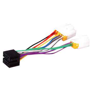
Wire Harness Offer Kinds Wire Harness Condition
.jpg)
Wire Blower Motor Resistor Harness.

Wiring Harness Automotive Wiring Diagrams And Electrical Diagrams.

2009 Civic Ex Engine Wire Harness Circuit Schematic.

Wiring Harness Assembly Mwh 03 China Wires Cables.
Wiring Harness Mediumsue0009fig 22 016e Jpg.

Fog Light Wiring Harness With Switch Kts Fog Lamp Wire Harness Fit.
Wiring Harness Mediumsue0175fig 37 81bc Jpg.

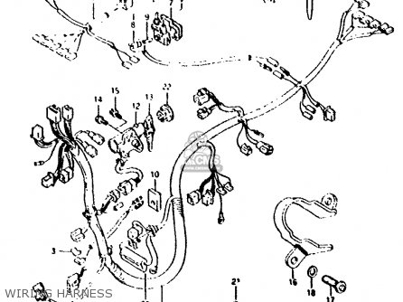
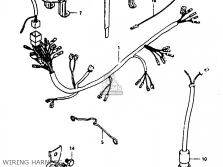
The Following Wiring Harness And Cable Routing Diagram Apply For.

Wire Harness Offer Many Kinds Of Wire Harness Used For Air Condition.

Wiring Harness And Cable Connection Diagram Here Source Manual.
Instructions Assemble Cat6 Plug Cable Clip Solid Stranded Shielded

Way Trailer Wiring Diagram And Connectors Pinout Circuit Schematic.

The Exact Sequence Represented In The Wiring Diagram Labeled 568b.

Jaguar Xj6 Series 3 Car Schematic Diagram 1979 1986 Circuit.

Honda Transalp Xl600v Electrical Wiring Diagram 1990 1999.

Cat6 568 B Wiring Diagram Png.

Bmw L6 M6 Electrical Troubleshooting And Wiring Diagram 87.

Atv Sportsman 800 Efi 6 6 Complete Wiring Diagram Circuit Schematic.
Instructions Assemble Cat6 Plug Cable Clip Solid Stranded Shielded.

Arctic Cat Snowmobile Z570 Carburetor Schematic Diagram.

Card When The Phone Rings The Wiring For Both Standards Is Below.
Kenwood Dv3100 Navigation System Wiring Harness Diagram

Find More Information About 1947 Harley Davidson Wiring Diagram Here.

Honda Accord Coupe 94 Fan Controls Circuit And Wiring Diagram.
Kenwood Kna Dv3100 Dvd Navigation System Wiring Harness Diagram.

Ktm 250 525 Sx Mxc Exc Electrical System And Wiring Diagram.
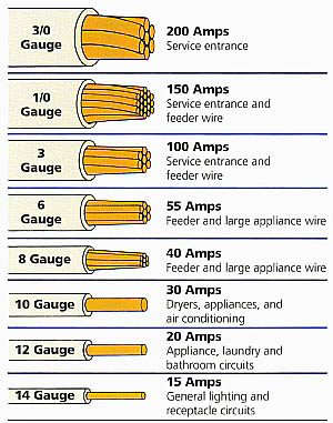
Wire The Smaller The Gauge Number The Larger The Conductor Size.

Jeep Grand Cherokee Radio Adaptor Wiring Harness Circuit Schematic.

Wiring Diagram Here Page 1 And Page 2 Source Autolib Diakom.

The Following Schematic Shows A Typical Diagram Schematic Of Polaris.

System And Wiring Diagram Here 60 Pages Of Pdf File Docs.

Cassette Cd And 6 Speakers Audio System Wiring Circuit Schematic.
Tuesday, June 4, 2013
Electrical Wiring Harnesses Trader Electrical Wiring Harnesses India

Wiring Harness China Wire Harness Wiring Harnesses.

Electrical Wiring Harnesses Trader Electrical Wiring Harnesses India.

Hid Kit Wire Relay Harness Harness.

Automotive Wireharness China Fuse Fuse Box.

Wiring Harness Wiring Harness Importer Manufacturer Supplier.

Rear Wire Harness Repair Layout Bmw E34 Touring Rear Wire Harness.
Wire Harness Wire Harness.
1992 1995 Tbi Stand Alone Wire Harness.
Wiring Harness Pins.

Wiring Harness For Cng Kit Wiring Harness For Cng Kit Exporter.
Subscribe to:
Posts (Atom)