Saturday, August 31, 2013

2 4GHz WiFi ISM Band Scanner Assembly Using the Scanner Part 3

2.4GHz WiFi & ISM Band Scanner. Description and Schematic - Part 1

2.4GHz WiFi & ISM Band Scanner. Firmware and Sowtware - Part 2

 
Assembly

Because the circuit was so simple I took the easy way out and assembled it on a piece of veroboard. Nowadays I would design my own printed circuit board (see custom PCBs).

Rather than finding a connector for the Cypress module I simply soldered single core hookup wire directly to the connector pins. This supported the module and allowed me to position it away from the microcontroller to minimise interference.

The USB cable was made from a standard USB cable with type A and B connectors, I just cut off the B connector and soldered the wires directly to the veroboard with half an inch of heatshrink tubing to keep it neat. That left the type A connector at the other end, ready to plug into the computer.

Note that the red and black wires in the USB cable are +5V and ground respectively. You should check these with a multimeter before soldering them in. The green wire is normally D+ and goes to pin 16 of the 18F2550 while the white is D- and goes to pin 15. The shield does not have to be connected.

The final touch was to drop the assembly into a standard UB5 "jiffy" box with a notch cut out for the USB cable to pass through.

2.4GHz WiFi & ISM Band Scanner

Using the Scanner

With nothing running in the immediate vicinity you will just see background noise, as shown in the screen shot below.

2.4GHz WiFi & ISM Band Scanner

Note that the vertical scale is not calibrated to any particular scale. In fact the scale is just the signal level "factor" reported by the Cypress radio module.

The base level signal represents the noise in the air and in the radio receiver part of the module.

The screenshot below shows a WiFi 802.11n wireless router running on channel 1 and located about 12 metres from the scanner. As you can see the 802.11n (and for that matter 802.11g) routers spread themselves over six channels.

2.4GHz WiFi & ISM Band Scanner

That is the good thing about using channel 1 and 13 for your WiFi setup, you get some unused channels on one side where your spectrum can spread into.

But, using channel 13 has its own problems.

The spectrum on the next screenshot is identical to the one above but this time my microwave oven was heating up dinner. Incidentally, the microwave oven was nothing special, just a domestic model and about 10 metres from the scanner.

2.4GHz WiFi & ISM Band Scanner

As you can see, it totally blotted out the higher frequency end of the band. All microwave ovens seem to use this part of the band and you cannot blame the microwave for their activity, as this was part of the reason for setting up the 2.4GHz ISM band in the first place. Avoiding the microwave oven interference and having some free spectrum on one side is the reason why channel 1 is the best choice for your router (assuming your neighbour has not got there first).

Finally, the screenshot shows a Bluetooth mouse communicating with a computer.

2.4GHz WiFi & ISM Band Scanner

Bluetooth hops all over the 2.4GHz band as it finds the best spots with the minimum of interference. Spikes all over the spectrum is a good indicator of Bluetooth activity. 

Continue reading...

Friday, August 16, 2013

Repair Samsung C3303 Champ Auto Charging Problem Solution

Repair Samsung C3303 Champ Auto Charging Problem Solution
Repair Samsung C3303 Champ Auto Charging Problem 
Repair Samsung C3303 Champ Not Charging Problem
Repair Samsung C3303 Champ Auto Charging Problem By Jumpers

Continue reading...

Thursday, August 15, 2013

The Battery is Transformed into a Mini LED Flashlight


When night fell, we urgently need to the light, especially in a small street without lights, we feel very terror, so we should always carry a flashlight. So today I introduced the useful household items for you, that is the mini LED flashlight.

This mini flashlight is a very simple structure, which is the use of led technology, a led installed in the traditional battery positive, and connected with negative by the built-in connection and switch,this best led flashlight can still be an ordinary battery, press the switch, it can shine to provide lighting When we need it. Taking into account the design does not change the basic structure of the battery, and led has the low cost, this mini LED flashlight still has its commercial potential, it can give people more convenient at least.
Continue reading...

Wednesday, August 14, 2013

Build a Low pass filter Circuit Diagram

This  Low-pass filter Circuit Diagram is useful where fast signal acquisition and high precision are required, as in electronic scales. The filters time constant is set by the 2 ohm resistor and the 1 µ capacitor until comparator No. 1 switches. The time constant is then set by the 1.5 ohm resistor and the 1 jtF capacitor. Comparator No. 2 provides a quick reset. The circuit settles to a final value three times as fast as a simple 1.5 ohm—1 µ¥ filter, with almost no dc error. 

 Low-pass filter Circuit Diagram

 Low-pass filter Circuit Diagram

 
Continue reading...

Tuesday, August 13, 2013

Telephone Call Recorder

Today phone has become an integral part of our lives. It is the most widely used communication tool in the world. Owing to its immense popularity & widespread use, there arises a necessity for call recording devices, which find application in call cent-res, stock broking firms, police, offices, homes, etc. Here they are describing a call recorder that makes use of only a few parts. But in order to understand its working, must first have the basic knowledge of standard phone wiring as well as a stereo plug.


In India, land-line rings primarily use RJ11 wiring, which has wireless-tip & ring. While tip is the positive wire, ring is the negative. & together they complete the phone circuit. In a phone line, voltage between tip & ring is around 48V DC when handset is on the cradle(idle line). In order to ring the phone for an incoming call, a 20Hz AC current of around 90V is superimposed over the DC voltage already present in the idle line. The negative wire from the phone line goes to IN1, while the positive wire goes to IN2. Further, the negative wire from OUT1 & the positive wire from OUT2 are connected to the phone. All the resistors used are 0.25W carbon film resistors & all the capacitors used are rated for 250V .


The negative terminal of To AUX IN is connected to pin one of the stereo jack while the positive terminal is connected to pins two and three of the stereo jack. This stereo jack, in turn, is connected to the AUX IN of any recording tool, such as computer, audio cas-setts player, CD player, DVD player, etc. Here they shall be connecting it to a computer. When a call comes in, around 90V AC current at 20Hz is superimposed over the DC voltage already present in the idle line.

This current is converted in to DC by the diodes & fed to resistor R1, which reduces its magnitude & feeds it to LED1. The current is further reduced in magnitude by the resistor R2 & fed to the right & left channels of the stereo jack, which are connected to the AUX IN port of a computer. Audio recording application,can be used to record the call. When a call comes in, needs to launch the audio recording program and start recording.

For phone recording, basically connect the stereo jack to the AUX IN port of the PC. Install the Audacity audio recorder . Run the executable Audacity file. By & sizable window, you will discover a drop-down box in the top right corner. From this box, select the AUX option. Now you are prepared to record any call. As soon as a call comes in, press the record button present in the Audacity main window & then pick up the phone receiver & answer the call. Press the cease button one time the call ends. Now go to the file menu & select the Export as WAVE option & save the file in a desired location.

You may change the worth of resistor R2 in case you require to change the output volume. You can use a variable resistor in series with R2 to vary the volume of the output. The recorded audio clip can be edited using different options in the Audacity application. You can assemble the circuit on a general-purpose PCB & enclose it in a small cabinet. Use an RJ11 connector & stereo jack for connecting the phone set & computer (for call recording). Phone cords can be used to connect to the phone line & the circuit. Use of a shielded cable is recommended to reduce disturbances in the recording. These may even be reduced by increasing the worth of R2 to about 15 kilo-ohms.
Continue reading...

Sunday, August 11, 2013

Input Impedance Booster Circuit

The input resistance of a.c.-coupled op amp circuits depends almost entirely on the resistance with which the d.c. setting is determined. If CMOS op amps are used, the input resistance is normally high, currently up to 10 MΩ. If a higher value is needed, a bootstrap circuit may be used. This enables the input resistance to be boosted artificially to a very high value, indeed In the circuit shown in the diagram, resistor R1 sets the d.c. point for IC1a. The terminal of the resistor linked to pin 7 of IC1 would normally be at earth potential, so that the input impedance would be 10 MΩ. Connecting the other terminal of the resistor to earth via IC1a and network C2-R3-R2 as far as d.c. is concerned results in the requisite d.c. setting of the op amp.

Circuit diagram:

Input Impedance Booster II Circuit Diagram

As far as alternating voltages are concerned, the input signal is fed back so that only a tiny alternating current flows through R1. Therefore, Rin=R1[(R2+R3)/R3]. With resistor values as specified, Rin is about 1 GΩ. One aspect must be borne in mind: the numerical value of (R2+R3)/R3 must not exceed 0.99. This means that the value of R3 cannot be less than 100 kΩ if the value of R2 is 10 MΩ. If these conditions are not met, the circuit will become unstable.


http://www.ecircuitslab.com
Continue reading...

Saturday, August 10, 2013

All Constructing Various DC Power Supplies Projects


One of the basic building blocks of electronics project is building your own DC power supplies from an AC source of 110 V.A.C or 220 V.A.C.The common DC voltages that are necessary to power up the devices are usually in the range of three V DC to 30 V DC. Usually the fixed types of DC voltages are 5V, 9V, 12V, 15V & 18V DC. With the advancement of know-how, lots of devices are using one.8 V DC these days. S M P S is becoming common these days as the demand for miniaturization due to space constraints increases.

Take note that for linear power supply projects, you need to make use of a step down power transformer to step down the AC voltage from the line voltage of 110 V.A.C or 220 V.A.C before using it to supply to the diode bridge.
Continue reading...

Friday, August 9, 2013

Home House Wiring Installation

House Wiring on 250 And 525 Sx  Mxc  Exc Electrical System And Wiring Diagram Here
250 And 525 Sx Mxc Exc Electrical System And Wiring Diagram Here.


House Wiring on House Wiring Diagram
House Wiring Diagram.


House Wiring on Free Wiring Diagrams   Download Free Wiring Schematics
Free Wiring Diagrams Download Free Wiring Schematics.


House Wiring on Wiring Diagram
Wiring Diagram.


House Wiring on Diagram Electrical Wiring
Diagram Electrical Wiring.


House Wiring on Telephone Socket Wiring   How To Do It
Telephone Socket Wiring How To Do It.


House Wiring on Thread  Wiring Clipsal Saturn Light Switches
Thread Wiring Clipsal Saturn Light Switches.


House Wiring on Mesa Whole House Wiring Services Provided By Amadeus Electric
Mesa Whole House Wiring Services Provided By Amadeus Electric.


House Wiring on Russell Residence  10007 Meadow Road Sw  Lakewood Wa 98499
Russell Residence 10007 Meadow Road Sw Lakewood Wa 98499.


House Wiring on Home House Wiring Installation
Home House Wiring Installation.


Continue reading...

Thursday, August 8, 2013

USB Battery Charger Circuit Rise

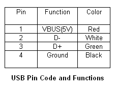
In recent years, the use of USB or Universal Serial Bus as a reliable communications interface in plenty of electronic devices have increased due to its increased speed, size and flexibility. It fundamentally consists of terminals VBUS(+5V supply), GROUND, D+ and D-. As plenty of of the devices run on rechargeable battery, it is now the trend to design the charging circuit that makes use of the power supply from the USB port to charge the rechargeable battery. This feature will make the devices more convenient to the users as the devices will get their power from the bus and requires no outside plug or cables.


USB Bus Powered Functions
Theres fundamentally three classes of USB functions on power that can be derived from the port.

  High-Power Bus The high power bus powered functions derived all its power from the VBUS and cannt draw over 100mA until its been configured. One time configured, it can draw up to five unit loads(500mA) by requesting it in its descriptor. At full load, it must be able to work between the VBUS voltage of four.75V and five.25V.

  Low-Power Bus The low power bus powered functions derived all its power from the VBUS and must not draw over one unit load (100mA) according to the USB standard. It must even be able to work between the VBUS voltage of four.40V and five.25V.

  Self-Power Self power functions can draw up to 100mA from the VBUS and the rest from its outside source. This is the most simplest to design.


USB Port Powered Battery Charger
This application circuit makes use of the MCP73853/MCP73855 linear charge management controllers for cost sensitive applications. They are specially designed for USB applications and adhere to all the USB specifications governing the USB power bus. The circuit below makes use of the MCP73855 to design a USB powered Lithium Ion/Lithium Polymer battery charger by deriving the power from the USB port.
Continue reading...

Wednesday, August 7, 2013

Protectors Circuit on SMPS power supply


The simplest example SMPS which still uses 3 transistors (C3807, A1015 and power transistors) classic problem that often occurs is: - Problem in the feedback circuit can cause the output voltage B + over so that it can endanger the aircraft as a whole. For example elco erupted, pcb burnt burnt by over-heated, horizontal transistor short.

- Problem on feedback circuits may cause power regulator transistor is damaged due to over current transistor (eg, due to the 47k resistor transistor circuit on the secondary error detector value is delayed).
- If the input ac voltage drops can cause the power regulator transistor is damaged, due to over current transistor If the secondary there is a power transistor short can cause damage over current regulator.
- Protectors are designed to make the SMPS SMPS "reliable will not be damaged" if there are things that go wrong as mentioned above. 

Switching Mode Power Supply protect Circuit
SMPS Circuit

SMPS circuit using IC systems generally are designed with a surge protector, which include:
  • Over voltage protector (OVP)
  • Over current protector (OCP)
  • Over load protector
  • Short circuit protector
  • Over temperature protector

Continue reading...

Tuesday, August 6, 2013

170W AMPLIFIER BTL LM4651 LM4652 CIRCUIT DIAGRAM

170W AMPLIFIER BTLLM4651 & LM4652 CIRCUIT DIAGRAM

IC LM4651 is a integrated conventional pulse width modulator driver IC. The IC contains short circuit, under voltage, over modulation, and thermal shut down protection circuitry. The LM4651 also contains a standby function which shuts down the pulse width modulation minimizing supply current.

IC LM4652 is a fully integrated H-bridge power MOSFET IC in a TO-220 power package. The LM4652 has a temperature sensor built in to alert the LM4651 when the die temperature of the LM4652 exceeds the threshold. Together, these two ICs form a simple, compact high power audio amplifier solution complete with protection normally seen only in Class AB amplifiers. Few external components and minimal traces between the ICs keep the PCB area small and aids in EMI control.

Absolute Maximum Ratings LM4651 & LM4652

  • Supply Voltage ± 22V
  • Output Current (LM4652) 10A
  • Power Dissipation (LM4651) 1.5W
  • Power Dissipation (LM4652) 32W
  • ESD Susceptibility (LM4651) 2000V,
  • ESD Susceptibility LM4652 (pins 2,6,10,11) 500V
  • ESD Susceptibility (LM4651) (Note 5) 200V
  • ESD Susceptibility LM4652 (pins 2,6,10,11) 100V
  • Junction Temperature 150°C
  • Soldering Information N, TA and TF Package (10 seconds) 260°C
  • Storage Temperature -40°C to + 150°C
Continue reading...

Monday, August 5, 2013

Twin T RC Notch Filter

The two T-notch filter can be used to block unwanted frequencies or if placed in an op amp as a bandpass filter. the notch frequency occurs where the capacitive reactance equals the resistance (Xc = R) and if the values are close, the attenuation can be very high and the notch frequency virtually eliminated,Insertion of the filter depends on the load, the output is connected to the subject so that the resistors must be of much lower value than the load for minimal loss.

Twin-T RC Notch Filter Circuit diagram

For audio frequencies, the filter may act as a bass and treble boost circuit by attenuating the midrange. With 1.5K resistors and capacitors 0.1 uF, the band is in stop-10dB 500 Hz to 2 kHz. The depth and breadth of the reaction can be slightly adjusted to a value of 0.5 R and adding some resistance at the C-values,If the circuit is an operational amplifier is used as a bandpass filter, the response should be reduced to avoid oscillation.
Continue reading...

Sunday, August 4, 2013

Volt Switch Trolling Motor Wiring Diagram

Boat Wiring Diagram on Thread  Generic Boat Wiring Diagram By Silvertip Plus Navigation
Thread Generic Boat Wiring Diagram By Silvertip Plus Navigation.


Boat Wiring Diagram on Re  12 24 Volt Switch Trolling Motor Wiring Diagram
Re 12 24 Volt Switch Trolling Motor Wiring Diagram.


Boat Wiring Diagram on Navigation Lights Wiring  A Wiring Diagram
Navigation Lights Wiring A Wiring Diagram.


Boat Wiring Diagram on Kevin Questions About Boat Wiring
Kevin Questions About Boat Wiring.


Boat Wiring Diagram on Bass Tracker   Tracker   Suntracker Boat Covers   Ameri Brand
Bass Tracker Tracker Suntracker Boat Covers Ameri Brand.


Boat Wiring Diagram on Am Looking For An Electrical Wiring Diagram Schematic For 1996 Ebbtide
Am Looking For An Electrical Wiring Diagram Schematic For 1996 Ebbtide.


Boat Wiring Diagram on Switch Panels   Fishing Boat Wiring
Switch Panels Fishing Boat Wiring.


Boat Wiring Diagram on Wiring Diagram 1995 Chevy Tahoe Wiring Diagram
Wiring Diagram 1995 Chevy Tahoe Wiring Diagram.


Boat Wiring Diagram on Wiring 12v Marine Tachometer Diesel Alternator Instructions   How To
Wiring 12v Marine Tachometer Diesel Alternator Instructions How To.


Boat Wiring Diagram on Trailer Wiring Diagram And Information   Tridentuk Com
Trailer Wiring Diagram And Information Tridentuk Com.


Continue reading...

Saturday, August 3, 2013

Door Handle Alarm Circuit Using Transistor

The automatic door handle alarm circuit gives a audible alarm and glows a LED when somebody touches the handle of the door. The circuit is latching type and continues to produce sound until it is switched off.


The transistor Q1 is wired as an astable multi vibrator whose output is used to bias transistor Q2 to conduction. As a result the transistor q3 and LED are in OFF state. When someone touches the handle, the capacitance of the human body damps the oscillations of Q1.The cuts the biasing of Q2 and it goes OFF.As a result the current flows to the base of Q3 , it conducts and LED glows. If the switch S1 is ON the transistor pairs Q4&Q4 which is wired in the latching mode is triggered and the Buzzer Z1 is activated. When the person removes his hand from door handle the LED goes OFF but the buzzer continues to beep. The only way to mute the buzzer is to open the switch S2. All capacitors must be rated 15V.

A 9V battery or 9V DC power supply can be used to power the circuit. To make L1 wind 25 turns of 0.4 mm enameled copper wire on resistor R2 and solder the ends of the wire to the resistor leads. This unit will stand for the R2 as well as L1 because both are parallel in the circuit. A readily available 10mH inductor can be used for L2. Connect the point A in the circuit to the door handle using a long wire.


Continue reading...

Friday, August 2, 2013

Volkswagen Cabriolet Cruise Control Wiring Schematic

Wiring Harness on Car Pak Electrical Wiring Harness And Sockets Catalog   Circuit
Car Pak Electrical Wiring Harness And Sockets Catalog Circuit.


Wiring Harness on 250 And 525 Sx  Mxc  Exc Electrical System And Wiring Diagram Here
250 And 525 Sx Mxc Exc Electrical System And Wiring Diagram Here.


Wiring Harness on Fiat Spider 124 Electrical Schematics And Wiring Harness 80     82
Fiat Spider 124 Electrical Schematics And Wiring Harness 80 82.


Wiring Harness on Here Is The Wiring Diagram For The Trailer Lights
Here Is The Wiring Diagram For The Trailer Lights.


Wiring Harness on Polaris Trail Boss 330 Magneto Wiring Harness   Circuit Schematic
Polaris Trail Boss 330 Magneto Wiring Harness Circuit Schematic.


Wiring Harness on Volkswagen Cabriolet Cruise Control Wiring Schematic
Volkswagen Cabriolet Cruise Control Wiring Schematic.


Wiring Harness on Wiring Harness For Hid Ballast  Price  Suppliers  Manufacturers
Wiring Harness For Hid Ballast Price Suppliers Manufacturers.


Wiring Harness on Honda Prelude Wiring Harness Routing And Ground Location  88
Honda Prelude Wiring Harness Routing And Ground Location 88.


Wiring Harness on Fog Light Wiring   Harness   Vw Bora   Relais
Fog Light Wiring Harness Vw Bora Relais.


Wiring Harness on Anti Theft System And Alarm Circuit Wiring Diagram   Circuit Schematic
Anti Theft System And Alarm Circuit Wiring Diagram Circuit Schematic.


Continue reading...

Thursday, August 1, 2013

Super Ni Cd Battery Charger 12 18V Circuit Diagram

A clever charger circuit that safely can charge any Ni-Cd battery. Offers charge current sellection, polarization detection and protection and the ability to connect many batterys in siries. Ni-Cd bateries can be recharged more than 1000 times before become useless. the charging current shoud be the 1/10 of the (Ah) of the battery. The bateries need 14 hours to be fully charged.Swhitch S2 is the current selection as folows: 50mA, 200mA and 400mA. LED D10 is the indicator for proper batery connection and/or wrong polarity checking. LED D9 is the charging indicator. The transformer is a 220V/2x12V 0.5A. 

Super Ni-Cd Battery Charger 12-18V Circuit Diagram


Super Ni-Cd Battery Charger 12-18V Circuit Diagram


 PARTS LIST
R1,R4,R5=10K 
R2,R3=100K 
R6,R8,R10=1K 
R7=820 
R9=100 
R11=15 
R12=3,9 
R13=1,8 
C1=1000uF/40v 
C2=470pf 
D1-D4,D6=1n4001-7 D7,D8=1n4148 
D9,D10=LED IC=741 
TR1=BC548 
TR2=BD137 
TR3=2N3055

Datasheet file1: Click here to download LM741.pdf datasheet.
Datasheet file2: Click here to download BC548.pdf datasheet.
Datasheet file3: Click here to download BD137.pdf datasheet.
Datasheet file4: Click here to download 2N3055.pdf datasheet.

Continue reading...